10. Applications of Laplace Transforms
Circuit Equations
There are two (related) approaches:
- Derive the circuit (differential) equations in the time domain, then transform these ODEs to the s-domain;
- Transform the circuit to the s-domain, then derive the circuit equations in the s-domain (using the concept of "impedance").
We will use the first approach. We will derive the system equations(s) in the t-plane, then transform the equations to the s-plane. We will usually then transform back to the t-plane.
Example 1
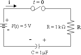
Consider the circuit when the switch is closed at `t=0`, `V_C(0)=1.0\ "V"`. Solve for the current i(t) in the circuit.
Answer
Substituting in the circuit equation `1/Cinti\ dt+Ri=V`, we obtain:
`1/10^(-6) inti\ dt+10^(3)i=5`
Multiplying throughout by 10−6 gives:
`inti\ dt+10^(-3)i=5xx10^(-6)`
Taking Laplace transform of both sides:
`(I/s+1/s[inti\ dt]_(t=0))+10^(-3)I` `=(5xx10^(-6))/s`
This presents us with a possible dilemma. How can we find the value of `intidt` at `t=0` if we don't know what `i` is yet? (The question asks us to find the current, `i`.)
To address this, we need to make use of the initial condition given in the question, `V_C(0)=1.0` and the fact `V_C=1/C[intidt]`.
Putting these together gives:
`V_C(0)=1/C[intidt]_(t=0)=1`
Therefore in this example: `[inti\ dt]_(t=0)=C`, that is:
`[inti\ dt]_(t=0)=10^(-6)`
Notation note: `[intidt]_(t=0)=q_0`, the initial charge.
Returning to our problem and substituting:
`(I/s+10^(-6)/s)+10^(-3)I=(5xx10^(-6))/s`
Collecting I terms and subtracting `10^(-6)/s` from both sides:
`(1/s+10^(-3))I=(5xx10^(-6))/s-10^(-6)/s`
`=(4xx10^(-6))/s`
Multiply throughout by `s`:
` (1+10^(-3)s)I=4xx10^(-6)`
Solve for `I`:
` I=(4xx10^(-6))/(1+10^(-3)s)` `=(4xx10^(-3)) 1/(1000+s)`
Finding the inverse Laplace transform gives us the current at time `t`:
`i=4xx10^(-3)e^(-1000t)`
Graph of `i=4xx10^(-3)e^(-1000t)`.
Example 2
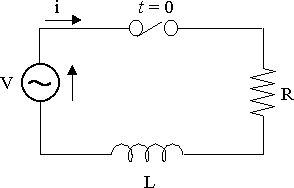
Solve for i(t) for the circuit, given that V(t) = 10 sin5t V, R = 4 W and L = 2 H.
Answer
`Ri+L(di)/(dt)=V`
`4i+2(di)/(dt)=10 sin 5t`
`4I+2(sI-i(0))=10 5/(s^2+25)`
Assume `i_0=i(0)=0`.
`4I+2sI=50/(s^2+25)`
`(2+s)I=25/(s^2+25)`
So
`I=25/((s+2)(s^2+25))` `=A/(s+2)+(Bs+C)/(s^2+25)`
`25 = A(s^2+ 25) + (Bs + C)(s + 2)`
We need to solve for A, B and C.
First, let `s = −2` and this gives
`25 = 29A`
Thus `A = 25/29`
Next, we equate coefficients of `s^2`:
`0=A+B` gives `B=-25/29`
Equating coefficients of `s`:
`0=2B+C` gives `C=50/29`
So
`I=25/((s+2)(s^2+25))`
`=25/(29(s+2))-25/29 s/(s^2+25)` `+50/29 1/(s^2+25)`
`=25/29(1/(s+2)-s/(s^2+25)+` `{:2/5 5/(s^2+25))`
So we have
`i=25/29(e^(-2t)-cos 5t+2/5sin 5t)\ "A"`
Here is the graph of `i(t)`:
Graph of `i(t)=25/29(e^(-2t)-cos 5t+2/5sin 5t)`.
Example 3
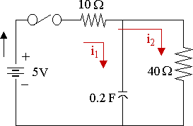
In the circuit shown below, the capacitor is uncharged at time t = 0. If the switch is then closed, find the currents i1 and i2, and the charge on C at time t greater than zero.
Answer
NOTE: We could either:
- Set up the equations, take Laplace of each, then solve simultaneously; or
- Set up the equations, solve simultaneously, then take Laplace.
It is easier in this example to do the second method. In many examples, it is easier to do the first method.
For the first loop, we have:
`R(i_1+i_2)+1/Cinti_1=E`
`10(i_1+i_2)+1/0.2inti_1=5`
`10(i_1+i_2)+5inti_1=5`
`2i_1+2i_2+inti_1=1\ \ \ ...(1)`
For the second loop, we have:
`10(i_1+i_2)+40i_2=5`
`10i_1+50i_2=5`
`2i_1+10i_2=1`
`i_2=1/10(1-2i_1)\ \ \ ...(2)`
Substituting `(2)` into `(1)` gives:
`2i_1+1/5(1-2i_1)+inti_1dt=1`
Simplifying:
`8/5i_1+inti_1dt=4/5`
Multiply throughout by `5`:
`8i_1+5inti_1dt=4`
Next we take the Laplace Transform of both sides.
Note:
`Lap{inti_1dt}=I_1/s+1/s[inti_1(t)dt]_(t=0)`
`=I_1/s+q_0/s`
In this example, `q_0=0`. So `Lap{inti_1dt}=I_1/s`
`8I_1+5(I_1/s)=4/s`
`(8+5/s)I_1=4/s`
` (8s+5)I_1=4`
` I_1=4/(8s+5)` `=1/2 1/(s+5/8)`
Now taking Inverse Laplace:
`i_1=1/2e^(-5/8t)`
And using result (2) from above, we have:
`i_2=1/10(1-2i_1)`
`=1/10(1-(2)1/2e^(-5/8t))`
`=1/10(1-e^(-5/8t))`
For charge on the capacitor, we first need voltage across the capacitor:
`V_C=5-10(i_1+i_2)`
`=5-10(1/2e^(-5/8t)+` `{:1/10(1-e^(-5/8t)))`
`=4-4e^(-5/8t)`
So, since `V_C=q/C`, we have:
`q=CxxV_C`
`=0.2xx(4-4e^(-5/8t))`
`=0.8(1-e^(-5/8t))` C
Graph of q(t):
Graph of `q(t)=0.8(1-e^(-5/8t))`.
The charge builds up to `0.8` C (but never quite reaches it).
Example 4
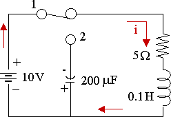
In the circuit shown, the capacitor has an initial charge of 1 mC and the switch is in position 1 long enough to establish the steady state. The switch is moved from position 1 to 2 at t = 0. Obtain the transient current i(t) for t > 0.
Answer
Position 1, after a 'long time': `i_0=10/5=2\ "A"`
Position 2: (`t>=0`)
We apply `sum"emf"` (that is, sum of the electromotive force), and consider the sum of the potential difference across elements.
In position 2, there is no emf.
`5i+0.1(di)/(dt)+1/(200xx10^(-6))inti\ dt` `=0`
`5i+0.1(di)/(dt)+5000inti\ dt=0`
Finding Laplace Transform:
`5I+0.1(sI-i_0)+5000(I/s+q_0/s)` `=0`
`5I+0.1(sI-2)+` `5000(I/s+(10^(-3))/s)` `=0`
`5I+0.1sI-0.2+5000 I/s+5/s=0`
Multiplying by `10s`:
`50sI+s^2I-2s+50000I+50=0`
`(s^2+50s+50000)I=2s-50`
Solving for I and completing the square on the denominator gives us:
`I=(2s-50)/(s^2+50s+50000)`
`=(2s-50)/(s^2+50s+625+49375)`
`=(2s-50)/((s+25)^2+49375)`
`~~2(s-25)/((s+25)^2+222.2^2)`
`=2((s+25)/((s+25)^2+222.2^2)` `{:-50/((s+25)^25+222.2^2))`
`=2((s+25)/((s+25)^2+222.2^2)` `{:-50/222.2 222.2/((s+25)^2+222.2^2))`
So the transient current is:
`i=2(e^(-25t)cos 222.2t` `{:-50/222.2e^(-25t)sin 222.2t)`
`=e^(-25t)(2 cos 222.2t-` `{:0.45 sin 222.2t)`
We could transform the trigonometric part of this to a single expression.
First, re-arrange the equation by taking the negative out front:
`i=-e^(-25t)(0.45 sin 222.2t -` `{: 2 cos 222.2t)`
Using the "Cosine Minus Case" identity given in the link above which says,
`a sin θ − b cos θ = −R cos (θ + α)`, we aim to solve:
`0.45 sin 222.2t - 2 cos 222.2t` ` = -R cos(222.2t + α) `
In this case we have `a=0.45` and `b=2,` giving us:
`R=sqrt(a^2+b^2)` `=sqrt(0.45^2 + 2^2)=2.05`, and
`alpha="arctan"a/b = "arctan"0.45/2` `=0.22131`
So we can write `0.45 sin 222.2t - 2 cos 222.2t` ` = - 2.05 cos(222.2t+0.22)`
This gives us (on multiplying both sides by `-1`):
`i=2.05 e^(-25t)cos(222.2t+0.22)` A
Here's the graph:
Graph of `i(t)=2.05 e^(-25t)cos(222.2t+0.22)`.
Example 5
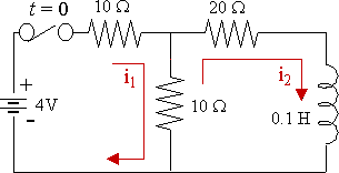
The system is quiescent. Find the loop current i2(t).
Answer
Quiescent implies i1, i2 and their derivatives are zero for t = 0, ie
i1(0) = i2(0) = i1’(0) = i2’(0) = 0.
For loop 1:
`10i_1+10(i_1-i_2)=4`
`20i_1-10i_2=4`
`10i_1-5i_2=2`
`i_1=1/10(2+5i_2)\ \ \ ...(1)`
For loop 2:
`20i_2+0.1(di_2)/(dt)+10(i_2-i_1)=0`
`-10i_1+30i_2+0.1(di_2)/(dt)=0`
`-100i_1+300i_2+(di_2)/(dt)=0`
Substituting our result from (1) gives:
`-100xx1/10(2+5i_2)+300i_2+(di_2)/(dt)` `=0`
`-10(2+5i_2)+300i_2+(di_2)/(dt)=0`
`250i_2+(di_2)/(dt)=20`
Taking Laplace transform:
`250I_2+(sI_2-i_2(0))=20/s`
`(250+s)I_2=20/s` since `i_2(0)=0`
`I_2=20/(s(s+250))`
Let `20/(s(s+250))=A/s+B/(s+250)`
So `20=A(s+250)+Bs`
`20=250A \ \ →\ \ A=20/250=2/25`
`A+B=0 \ \ →\ \ B=-2/25`
So `20/(s(s+250))=2/25(1/s-1/(s+250))`
Taking Inverse Laplace:
So `i_2=2/25(1-e^(-250t))`
Graph of `i_2=2/25(1-e^(-250t))`.
The current builds up to `0.08` A (but never quite reaches it).
Example 6
Consider a series RLC circuit where R = 20 W, L = 0.05 H and C = 10-4 F and is driven by an alternating emf given by E = 100 cos 200t. Given that both the circuit current i and the capacitor charge q are zero at time t = 0, find an expression for i(t) in the region t > 0.
Answer
We use the following equation from before:
`Ri+L(di)/(dt)+1/Cinti\ dt=E`
and obtain:
`20i+0.05(di)/(dt)+1/10^(-4)inti\ dt` `=100 cos 200t`
After multiplying throughout by 20, we have:
`400i+(di)/(dt)+20xx10^4intidt` `=2000 cos 200t`
Taking Laplace transform and using the fact that i(0) = 0:
`400I+sI-i(0)+200000I/s` `=2000 s/(s^2+200^2)`
`400sI+s^2I+200000I` `=2000 s^2/(s^2+200^2)`
`(s^2+400s+200000)I` `=2000 s^2/(s^2+200^2)`
`I=` ` (2000 s^2)/((s^2+400s+200000)(s^2+200^2))`
Using Scientific Notebook to find the partial fractions:
`(2000 s^2)/((s^2+400s+200000)(s^2+200^2))`
`=(2000-s)/(s^2+400s+200000)+(-400+s)/(s^2+40000)`
So
`I=-(s-2000)/(s^2+400s+200000)` `+(s-400)/(s^2+200^2)`
`=-(s-2000)/(s^2+400s+40000+160000)` `+(s-400)/(s^2+200^2)`
`=-(s-2000)/((s+200)^2+400^2)` `+(s-400)/(s^2+200^2)`
`=-(s+200)/((s+200)^2+400^2)` `+2200/((s+200)^2+400^2)` `+s/(s^2+200^2)-400/(s^2+200^2)`
`=-(s+200)/((s+200)^2+400^2)` `+11/2 400/((s+200)^2+400^2)` `+s/(s^2+200^2)-2 200/(s^2+200^2)`
So
`i=-e^(-200t)cos 400t` `+11/2e^(-200t)sin 400t` `+cos 200t` `- 2 sin 200t`
NOTE: Scientific Notebook can do all this for us very easily. In one step, we have:
`Lap^{:-1:}` `{(2000 s^2)/((s^2+400s+200000)(s^2+200^2))}`
`=-e^(-200t)cos 400t+` `11/2e^(-200t)sin 400t+cos 200t-` ` 2 sin 200t`
Graph of `i=` `-e^(-200t)cos 400t+11/2e^(-200t)sin 400t+` `cos 200t-` ` 2 sin 200t`.
Transient part: `-e^(-200t)cos 400t+11/2e^(-200t)sin 400t` (using a different scale on the horizontal axis)
Graph of `i=-e^(-200t)cos(400t)+11/2e^(-200t)sin(400t)`.
Steady state part: `cos 200t-2 sin 200t`
Graph of `i=cos 200t-2 sin 200t`.
Example 7
A rectangular pulse `v_R(t)` is applied to the RC circuit shown. Find the response, v(t).
Graph of `v_R(t).`
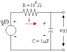
Note: v(t) = 0 V for all t < 0 s implies v(0-) = 0 V. (We'll use this in the solution. It means we take `v_0,` the voltage right up until the current is turned on, to be zero.)
Answer
Now `V_R(t)=u(t)-u(t-2)`
To solve this, we need to work in voltages, not current.
We start with `Ri+1/Cinti\ dt=V`.
The voltage across a capacitor is given by `v=1/Cinti\ dt`.
It follows that `C(dv)/(dt)=i`.
So for this example we have:
`RC(dv)/(dt)+v=u(t)-u(t-2)`
Substituting known values:
`RC=10^6xx10^-6=1`
Then
`(dv)/(dt)+v=u(t)-u(t-2)`
Taking Laplace Transform of both sides: `(sV-v_0)+V=1/s-(e^(-2s))/s`
Since `v_0=0`, we have:
`(s+1)V=1/s-(e^(-2s))/s`
`V=1/(s(s+1))-(e^(-2s))/(s(s+1))`
`=(1/s-1/(s+1))-(e^(-2s)/s-` `{:(e^(-2s))/(s+1))`
`=1/s-1/(s+1)-(e^(-2s))/s+(e^(-2s))/(s+1)`
So, taking inverse Laplace
`v=u(t)-e^(-t)*u(t)-` `u(t-2)+` `e^(-t+2)*u(t-2)`
NOTE: For the part: `Lap^{:-1:}{(e^(-2s))/(s+1)}`, we use:
`Lap^{:-1:}{e^(-as)G(s)}` `=g(t-a)*u(t-a)`
So we have:
`G(s)=1/(s+1)`
`g(s)=e^(-t)`
`a=2`
`Lap^{:-1:}{(e^(-2s))/(s+1)}=g(t-a)*u(t-a)`
`=e^(-(t-2))*u(t-2)`
`=e^(-t+2)*u(t-2)`
Solution Using Scientific Notebook
1. To find the Inverse Laplace:
`Lap^{:-1:}{1/(s(s+1))-(e^(-2s))/(s(s+1))}` `=1-e^(-t)-` `"Heaviside"(t-2)(1-e^(-t+2))`
2. To solve the original DE:
`(dv)/(dt)+v=u(t)-u(t-2)`
`v(0)=0`
Exact solution for v(t):
`v(t)="Heaviside"(t)` `-e^(-t)"Heaviside"(t)` `-"Heaviside"(t-2)` `+"Heaviside"(t-2)e^(-t+2)`
To see what this means, we could write it as follows:
`v(t)=(1-e^(-t))u(t)+` `(-1+e^(-t+2))*u(t-2)`
`=(1-e^(-t))*u(t)+` `(-1+e^(-t)e^2)*u(t-2)`
`=(1-e^(-t))*u(t)+` `(-1+e^(-t))*u(t-2)+` `e^(-t)(e^2-1)*u(t-2)`
`=(1-e^(-t))*(u(t)-u(t-2))+` `e^(-t)(e^2-1)*u(t-2)`
To get an even better idea what our solution for v(t) means, we graph it as follows:
Graph of `v=` `(1-e^(-t))*(u(t)-` `{:u(t-2))+` `e^(-t)(e^2-1)*u(t-2)`.
